The LRTimelapse Pro-Timer is the predecessor of the LRT PRO Timer, and a free Open Source DIY Intervalometer for timelapse, macro and astro photographers. I’ve developed it as a DIY Project and I’m sharing the build instructions with you for free. This intervalometer fulfills all my current requirements for shooting my timelapses.
If you’d rather buy than build, check out the new LRT Pro Timer.
I’ve started this intervalometer project because I couldn’t find a single intervalometer on the market that could satisfy all of my needs as a timelapse and astro photographer.
Note: A German version of this article can be found here.
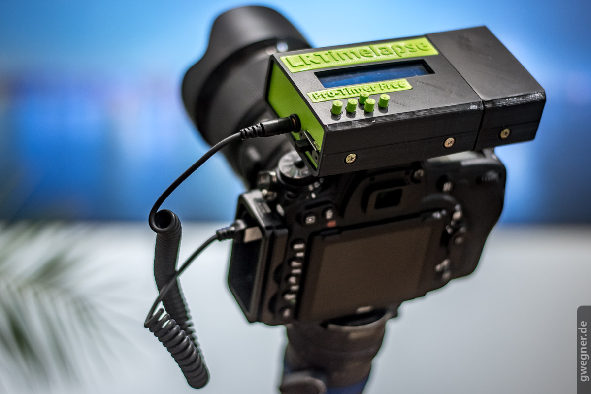
The LRTimelapse Pro-Timer Free works with any camera that has an analog remote trigger port. With very few exceptions, that’s every camera. It is based on an Arduino microcontroller, an LC-display and a small circuit board.
I’m making the necessary firmware, as well as the construction guidance, available to you free of charge. Furthermore, Christian Steinkrüger kindly developed a housing especially for this project. He also provided the 3D printing data free of charge. If you do not have access to a 3D printer you can, use any 3D printing service or ask Logodeckel.de, if they’d ship to your country.
The assembly of the LRTimelapse Pro-Timer Free is simple and should not take more than one or two hours. Apart from some hardware (more on that below), you will need an electronics soldering iron, a little bit of practical experience, or the help of somebody who has experience soldering, but it’s really nothing major.
This makes for a nice project on a free Saturday or Sunday, out of which you will get a useful tool and I am pretty sure that you will also learn something.
What can one do to improve an intervalometer?
There are hundreds of intervalometers available on the market. If you are immersed as deeply in timelapse photography as I am, you will soon find several disadvantages with them, such as:
- Unnecessary delay in triggering the autofocus signal (more can be found here) and other unnecessary delays which restrict the shooting interval;
- No indication of the number of the shots already taken;
- The remaining time will often not be displayed when you set the number of total shots;
- No way to change the interval smoothly over a certain period of time while shooting (Interval-Ramping);
- No way to completely switch off the Display during the timelapse;
- Intervals can only be set in full seconds;
- No real short intervals/ dark-times possible (the dark-time is the interval minus the exposure time);
- The devices are sometimes powered by proprietary batteries that are not easily available;
- The release cable is not removable;
- No ability to attach the intervalometer to the camera forcing you to hang it from the camera;
- Complex programming and operation, especially in dark conditions;
- Buttons which are hard to use in the dark, or when wearing gloves.
These are all issues that I’ve experienced with intervalometers I have purchased or that my workshop participants brought with them.
Cons of a smartphone-based solution for triggering the camera
There are some clever smartphone based solutions that meet some of my requirements, but my practical experience shows that the smartphone isn’t the perfect tool either to trigger the camera for timelapse. Some reasons for this are:
- For reliability it should be a cable-based solution, but then I would have to attach my smartphone to the camera. To prevent it hanging from the cable, I would need some extra holder;
- Wireless solutions aren’t reliable enough to trigger the camera. There is always the risk of the connection getting disconnected;
- A long timelapse shoot will drain the smartphone’s battery, so most likely, the smartphone will not survive the day before the it goes flat or requires it’s own external battery;
- While shooting, I can’t use my smartphone for other purposes such as taking photos, checking email, finding the next location, controlling the camera via Auto Holy Grail etc.;
- Smartphones won’t always guarantee an accurate timing of the intervals. Often one does not really get accurate intervals because the apps don’t have total control over the phone. The mobile operating systems can slow them down at any time, put them to sleep, or even quit completely. Unfortunately, you cannot have a total reliability on this..
When shooting the Holy Grail, I use my smart device to adjust the camera settings automatically with qDslrDashboard’s Auto Holy Grail – but for the reasons mentioned above, I do not use it to trigger the camera.
These are system-related disadvantages, making such solutions unusable for me in practice.
Based on these thoughts I decided to design and build my own intervalometer. My goal was to build an intervalometer which meets all my requirements while also being cheap and easy to build for everyone.
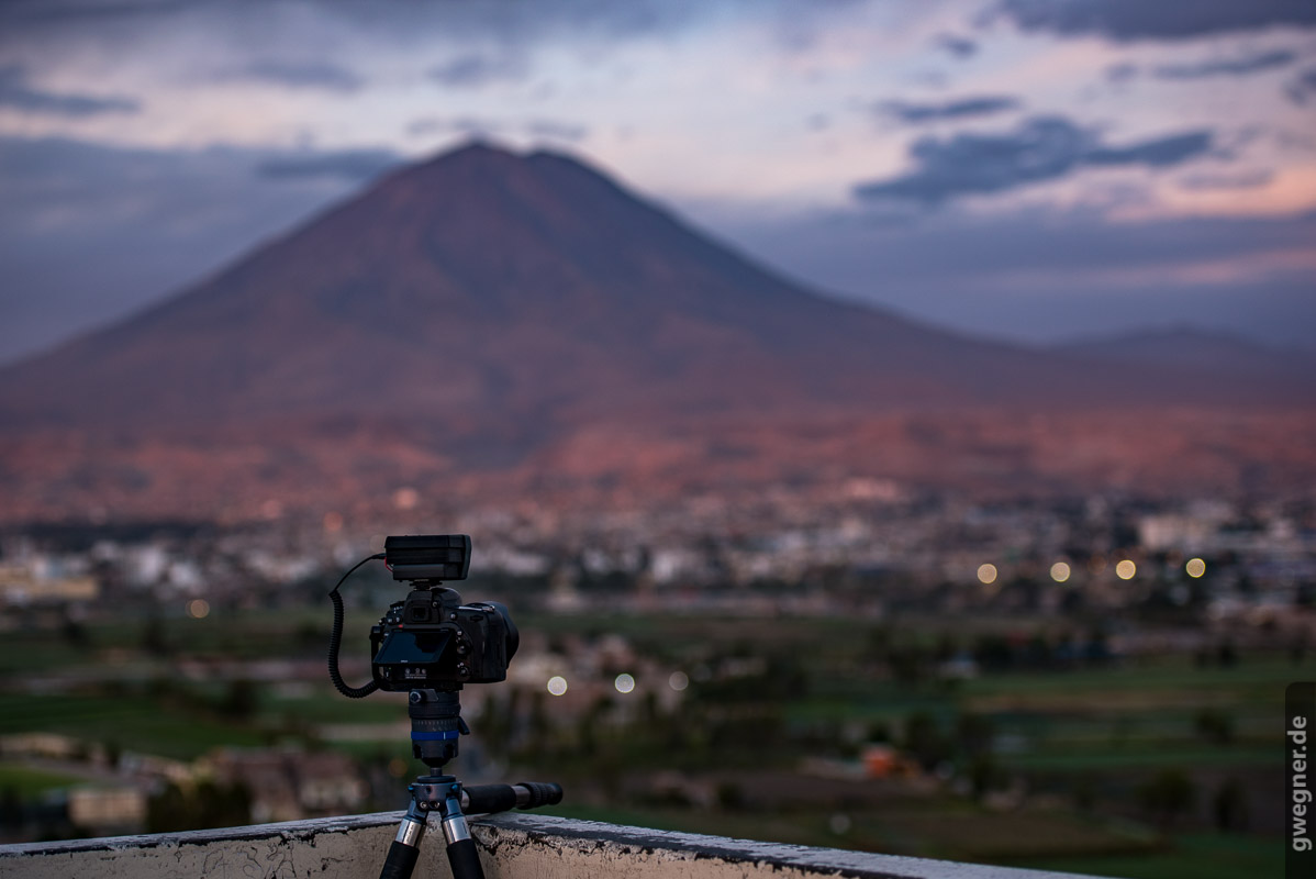
Shooting timelapse in Peru with a prototype of the LRTimelapse Pro-Timer Free
Advantages of the LRTimelapse Pro-Timer Free
- Fastest intervalometer I’ve ever used.
- Zero delay between capturing images (except the time the camera needs to store the image).
- Intervals adjustable in steps of 0.1 seconds.
- Default interval can be definied and saved.
- Optional operation of the camera in Bulb-Mode for exposure times longer then 30 Seconds (especially for Astro-Photography).
- Stepless interval-ramping (adjustment of the interval) on any intervals over any time.
- Toggle Illumination on/off with just a press of a button. You can as well define the brightness level of the illumination and save this as default.
- One mode to capture an infinite number of pictures, in this mode the captured pictures will be counted and the elapsed time displayed.
- or you can capture a given number of pictures, then remaining time and number of pictures left will be displayed.
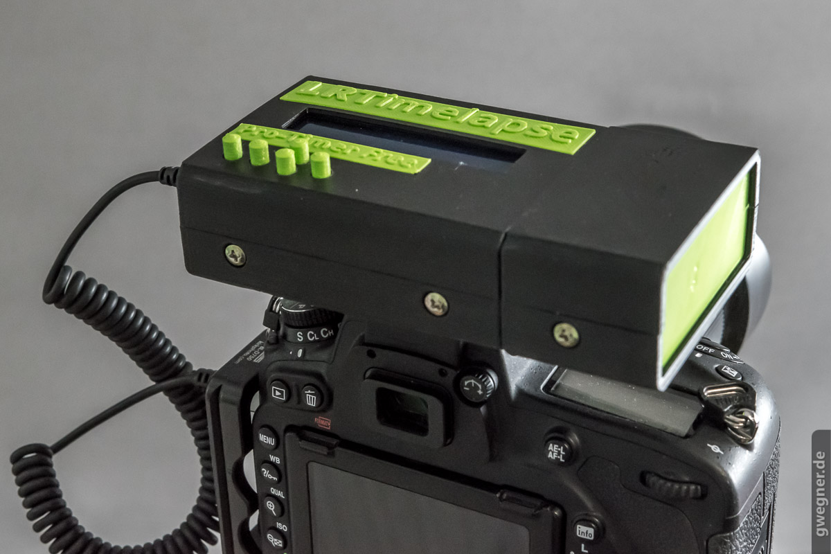
- Ability to attach the LRTimelapse Pro-Timer onto the hot shoe of the camera.
- Easy to operate.
- Large buttons, that are easy to feel and operate in the dark – even with
- Ability to trigger a motion controller with slave mode such as NMX or Emotimo Spectrum. This allows you to use the interval ramping even while shooting timelapse with motion control.
- Open Source software and case – this means only material costs for you.
- Community project that means a lot of fun!
Ready for a small do-it-yourself adventure? Here we go!
Required Components
- Arduino Uno (approx. US$25 – get the original one!)
- Sainsmart LCD Display Shield (approx. US$14)
- 2.5mm TRS jack socket (to connect camera release cable), for example here or here.
- Small piece of prototyping PCB / matrix board like shown in the images below
- NPN Transistor 2N2222 or BC337 (TO-92) for example BC337-16 or BC337-25 or BC337-40. If you want, you could also use an Optocoupler, for example the PC817 from Sharp (less than 1 US$).
- 1 KOhm resistor
- Some thin, insulated copper wire.
- Battery holder 4 AA with cable (not with clip!)
- On-off slide switch for example this one or similar
- A USB-A to USB-B cable, for the programming of the Arduino, which you most likely will find somewhere at home (look for an old printer-USB-cable)
- The housing, either printed yourself or bought from Logodeckel (see below)
- Some computer screws to close the housing
- A commercially available release cable for your camera. With one end having a 2.5mm TRS jack plug and on the other end just a normal plug for your camera. In case you do not own such a cable yet, you can just search for camera release cable <your camera> for example at Amazon or Ebay. Or ask your local camera dealer.
The total material cost (without housing) will be around $50 (US), most likely you will find some parts somewhere in your workshop, which may reduce costs even more. Although the LRTimelapse Pro-Timer free is cheaper than many commercial intervalometers, it is by far more powerful. Besides it’s fun to build, you will learn something and you’ll have something to be proud of at the end!
Connecting the Display-Shield
Please start by plugging the Display-Shield into the Arduino. Take care to plug in the pins correctly. If you take a look from the top at the display, the pins have to be aligned with the sockets at the top on the right side. The right-hand border of the circuit board of the Display-Shield has to be properly aligned with the circuit board of the Arduino. When aligned, carefully press the display shield onto the Arduino board.
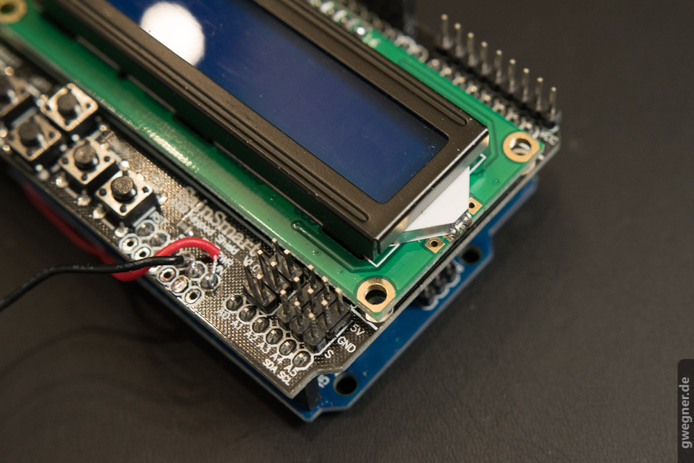
Both circuit boards have to be aligned on the right-hand side. The soldered cables on the left will follow later.
Now we can directly move on to the programming of the Arduino firmware. Later, we will complete the interface to the camera and the assembly of the housing.
Programming the Arduino
To program the Arduino with the sketch (Arduino firmware) I provide, you will need to download the Arduino IDE software tool. Don’t worry, you do not have to develop or code anything by yourself, we’ll only use the tool to upload the firmware.
Download of the Arduino IDE Software
Download and install the latest version of the IDE for your operating system. Let the installation run through with the standard settings including the USB drivers.
Connect the Arduino with the USB cable to a free USB port.
After starting the application you should see the following window:

Now open the Settings dialog via menu File → Preferences and remember the Sketchbook location or copy it to the clipboard.

Open this (remembered) folder in Explorer or Finder.
In the next step, download my sketch for the LRTimelapse Pro Timer Free.
Download “LRTPTF Arduino Sketch”
LRTimelapse-Pro-Timer-Free_0.92.zip – Downloaded 7847 times – 14.40 KBUpdate: Forum User Hans Vollmer has made some nice additions to the official firmware, which he released here. You might also try his version of the firmware.
Unzip the downloaded zip file to the folder you just opened.
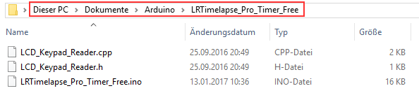
It is important that the LRTimelapse_Pro_Timer_Free folder is located in the sketch directory and contains those three files. (this will be OK if you have followed the steps above correctly but please check)
Now you can open the sketch (Arduino programs are called sketches) in the Arduino IDE.
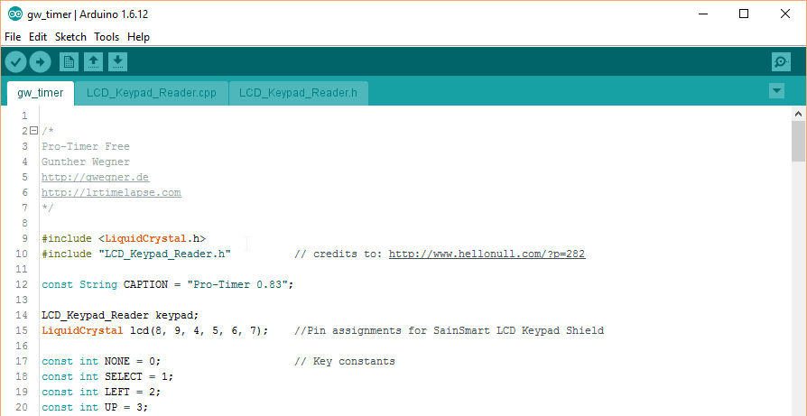
Go to menu File → Open, navigate to the folder with the sketch, and open the file LRTimelapse_Pro_Timer_Free.ino.
The IDE automatically loads all three files, which then looks like this:
Also, please check if the correct Arduino type is selected. In the menu, select Tools → Board. Check “Arduino / Genuino Uno” is selected. Please select it, if it’s not.

In the menu below, select the specified port once:
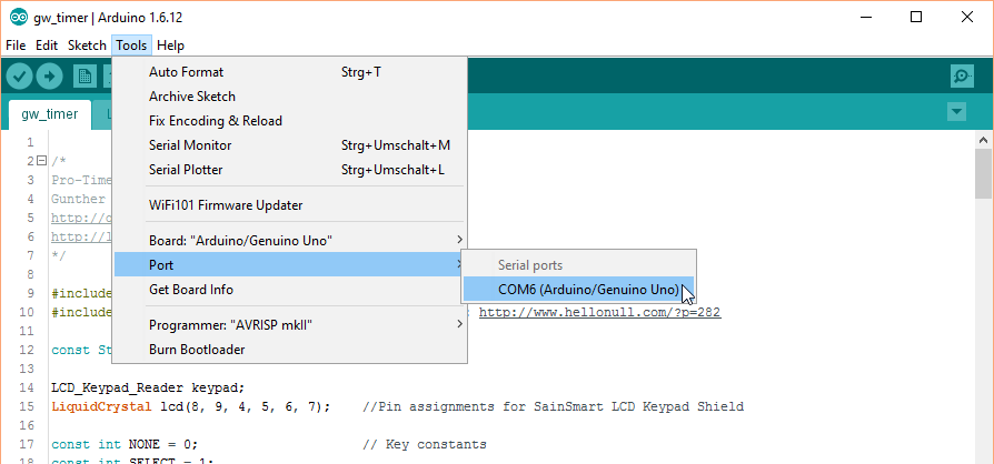
The port is assigned by the USB driver and may differ on your system.
Now go to menu Sketch → Check / Compile, which should go through without any error messages.
Next, you can upload the compiled sketch to the Arduino, which is easy. Just select menu Sketch →Upload.
After uploading, the Arduino reboots automatically and you should see the welcome message of the LRTimelapse Pro-Timer Free on the display!
Now you can start the first test without camera. The USB connection to your computer will be a sufficient power supply for now.
Note: If you don’t see anything on the display or the contrast is bad, take a small screwdriver and adjust the plastic screw in the upper left corner (square blue housing) above the display. This allows you to adjust the contrast of the display. Normally you have to do this only once at the initial test and never again.
Menu guide for the LRTimelapse Pro-Timer Free
After starting the timer, the welcome screen will briefly show and then you will see the menu. You can navigate with the buttons of the display shield.
The Up / Down buttons change values or switch between menu items, the Right button moves forward, the Left button moves back. The leftmost button turns the backlight off or on.
I designed the operation as logically as I could. Navigate through the menu points and try it out. The only thing which still does not work at this point is triggering the camera – the necessary connection is still missing. But we will get to that point in the next step.
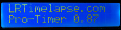
Welcome screen, Version 0.87
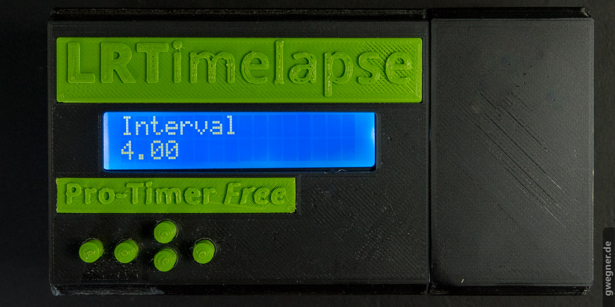
After the welcom screen the interval selector is being shown automatically, this is the “main screen” of the timer.
With the keys Up and Down you can now set the interval.
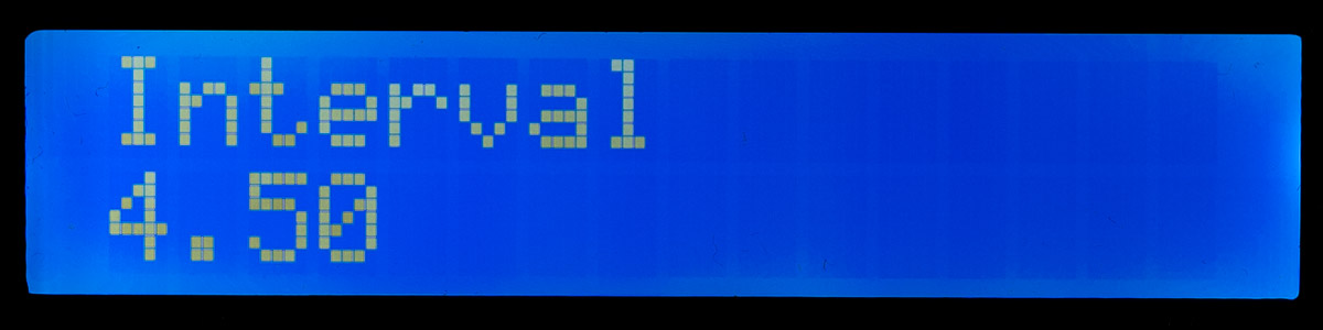
Interval setting in increments of 0.1 second
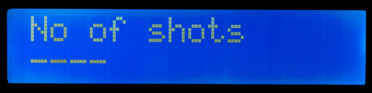
Number of shots (here the —- means infinity)
New in 0.87: After pressing Right, you now get a new menu, in which you can choose between M-Mode and Bulb-Mode.
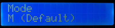
For regular time lapse shots, please select M-Mode and set the exposure time in the camera, as usual.
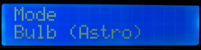
Only for astro-photography with exposure times >30 seconds, you can now choose the Bulb-Mode, and set it on the camera too. In this case you can control the exposure time via the LRTimelapse Pro Timer free.
If you set the exposure time here, it cannot be longer then the interval minus 0.5 seconds.
Any exposure will be visualised by a filled rectangle in the middle of the lower display row in this mode:
The filled rectangle shows that the camera is currently exposing.
Clicking on Right takes you to the next setting:

Number of shots to take (here 625)

Display while running after the total number of shots has been set: Current Image counter (3), Images left (R: 622), Interval (4.5 secs), Remaining time (T-HH:MM), Running time (HH:MM:SS).
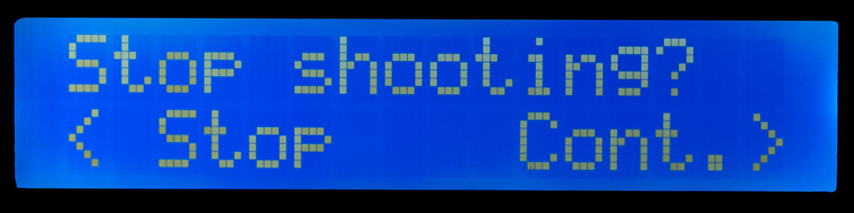
Confirmation required before really canceling the recording after a left-click from the current recording
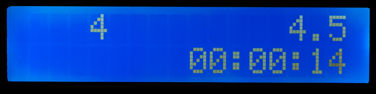
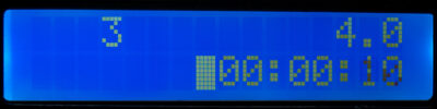
Display while running, if no maximum number of shots has been specified: Upper left: number of images, Upper right: interval, Bottom: Running time.
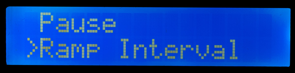
Right-click while shooting: Menu for Pause and Interval-Ramping

Duration of Ramping
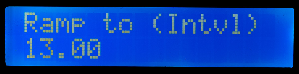
Target interval for Ramping

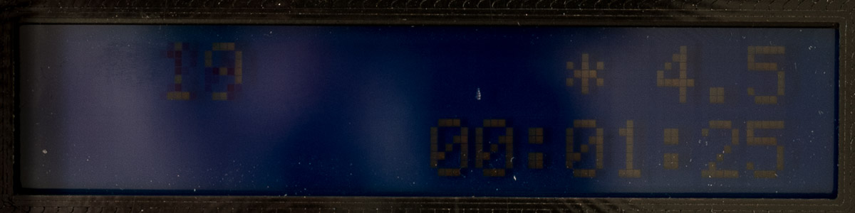
Display of a “*” during Interval Ramping on the running screen
With the button on the far left, the display can be switched off or on at any time.
Update: New in 0.87
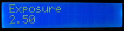
Apart from the new Bulb-Mode shown above, Version 0.87 also brings a new Single-Exposure screen. This allows you to easily do single exposures with the timer. It’s expecially useful for Long-Exposures in Bulb-Mode or test shots.
You will reach this new screen, by clicking Left from the main screen (interval screen).
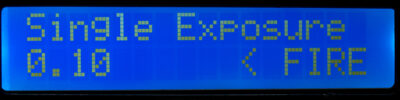
By default it’s set to Single Exposure and will trigger the camera with the shortest time possible. If you click on Left now, it will just trigger the camera – this can be usefull for test shots.
With Up / Down you can now define the exposure time, the display will switch to Bulb Exposure for longer times. Subsequently you should set the camera on Bulb then too.
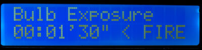
In this mode, you can do very long exposures. Firering the camera will happen when clicking Left. A counter will show the remaining time while exposing.
Any long time exposure can be interrupted by clicking Right. You’ll get a confirmation query then.
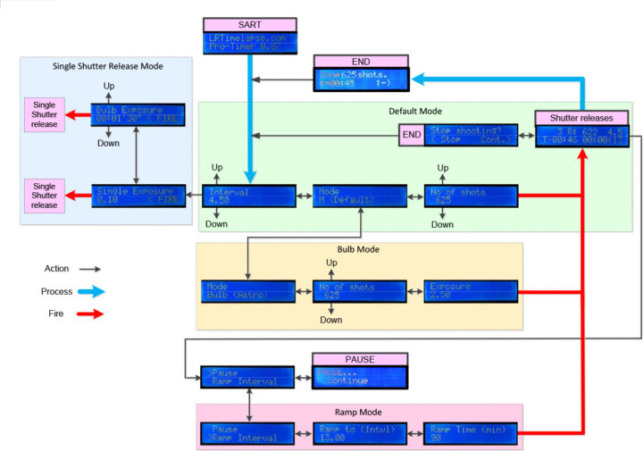
Flow-Diagram for the LRTPTF User-Interface
One of my users has created a nice flog-diagram covering the user interface, thank you Bernard!
Construction of the Interface Board
In order to trigger the camera we need a small circuit which will be triggered by the Arduino and ensures that the shutter release signal to the camera is pulled to ground. The circuit is not much more than a resistor and a transistor.
First, ensure the Arduino board is not still powered after the earlier screen tests by disconnecting the USB cable from the board.
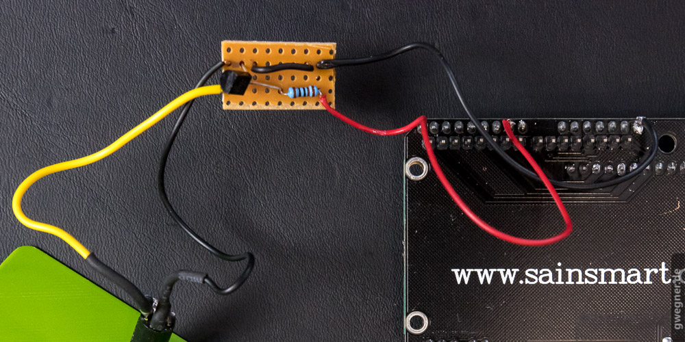
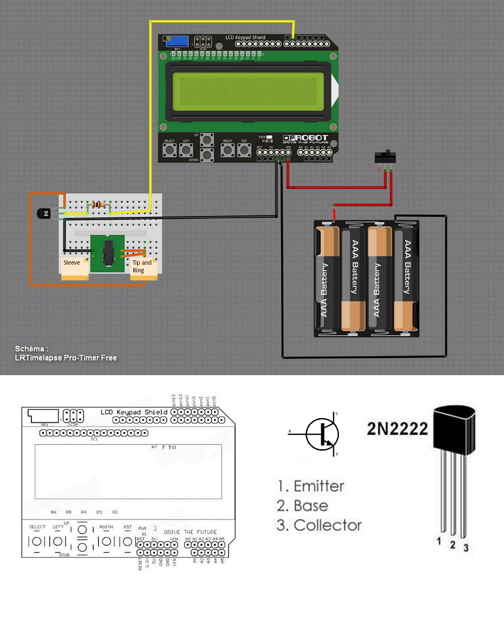
The easiest way to build the board is to use a small piece of matrix circuit board to solder the components onto and wire them appropriately. The best way to do this, is to set up the circuit as shown below.
On the left of the board you will find the connectors for the 2.5mm TRS jack socket, into which the camera release cable will be plugged. On the right hand side you can see the connections to the Arduino.
Here we need a ground (Arduino_GND), and the signal output Arduino pin P12 (Arduino_P12). R1 is the 1kOhm resistor, 2N2222A is the transistor. The alignment of the transistor is also shown below on the next photo.
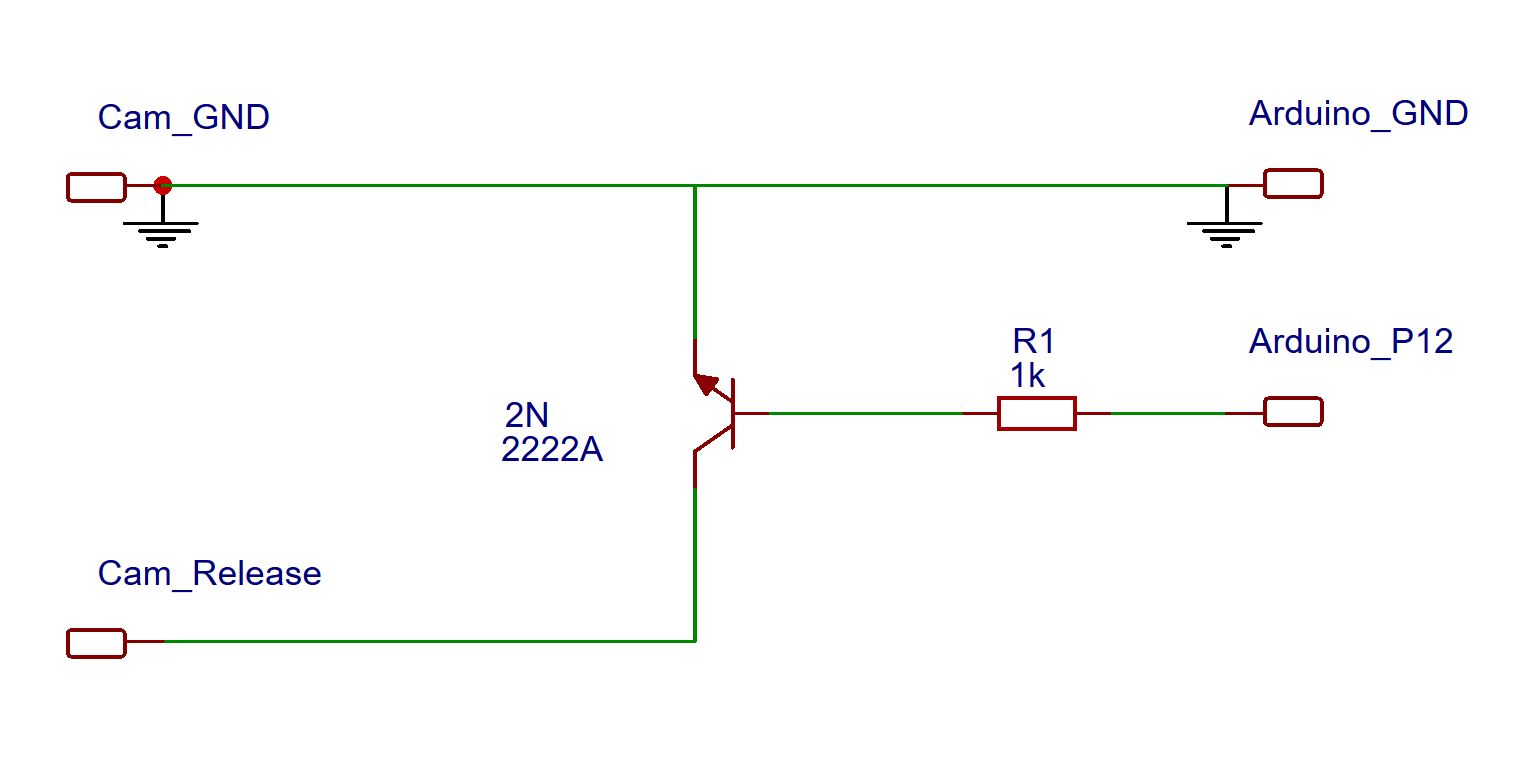
Circuit Diagram LRTimelapse Pro Timer
Here is a nice Diagram that forum-user mederic023 has drawn:
For the next steps you should now separate the Arduino from the display shield. We only need the Display-Shield for now, we will recombine the Arduino and the Display-Shield when we’re done.
The red cable, which is connected to the resistor, is soldered carefully to pin P12, which is the 8th pin counted from the upper left, when looking from the back side of the display shield board (the second last from the first block of pins).
The black ground-cable must be soldered to the pin on the far right of the second block. As I said, be careful when soldering, avoid producing a short circuit with adjacent pins.
On the other side (Cam_Release and Cam_GND) you now solder the 2.5mm TRS jack socket for the camera-trigger. Please install the socket in the outer wall of the housing first, as it has to inserted from the outside otherwise you will have to resolder it again later.
The black ground-cable is connected to the ground terminal of the 2.5mm TRS jack socket (which is the long contact in the middle, when you look from the rear of the micro-jack). I would recommend using a piece of shrink tubing after soldering, for insulation. Alternatively, a small piece of insulating tape will do.
Now solder the yellow cable shown in the photo to the other two contacts, connecting them. This allows us to trigger the focus and release the shutter at the same time (some cameras require focus to be triggered too, otherwise they don’t release). You can simply strip the end of the cable slightly longer and solder it to the first contact and then to the other contact. The only important thing is that it does not touch the ground terminal, that’s why you have insulated it earlier.
Reattach the Arduino now, as described above.
Now you can test the camera release. Connect a standard trigger cable with a micro-TRS plug the socket that you’ve just soldered and the other side into your camera.
Start the LRTimelapse Pro-Timer Free and it should now trigger your camera!
Power Supply
So far we’ve been using the USB connection to the computer as power supply which might be too cumbersome in the field. One alternative could be to power the LRT Pro-Timer by a powerbank with USB output. If you like to do so you only need to drill a hole in the housing where you can bring the USB cable in and subsequently use the Arduino USB port for power supply.
Personally I prefer the idea of a self-sustaining device and therefore utilised a battery holder for AA rechargeable batteries which fits exactly in the housing that Christian has designed. Please use 4 AA rechargeable batteries, I recommend Eneloop rechargeables. You can obtain 1,900 mAh Sanyo eneloop or a higher capacity 2550 mAh Panasonic eneloop pro battery – (eneloop batteries have a very low self discharge rate).
This battery pack provides 4 x 1.2V, that’s 4.8V when using rechargeables, perfect to operate the Arduino at the 5V input. Please don’t use regular disposable batteries, since they are not only bad for the environment but also they would provide 4 x 1.5V = 6V which is too much for that input.
One set of those rechargeable batteries, for example, was sufficient for one week of intense timelapse photography in Norway without recharging, even at low temperatures.
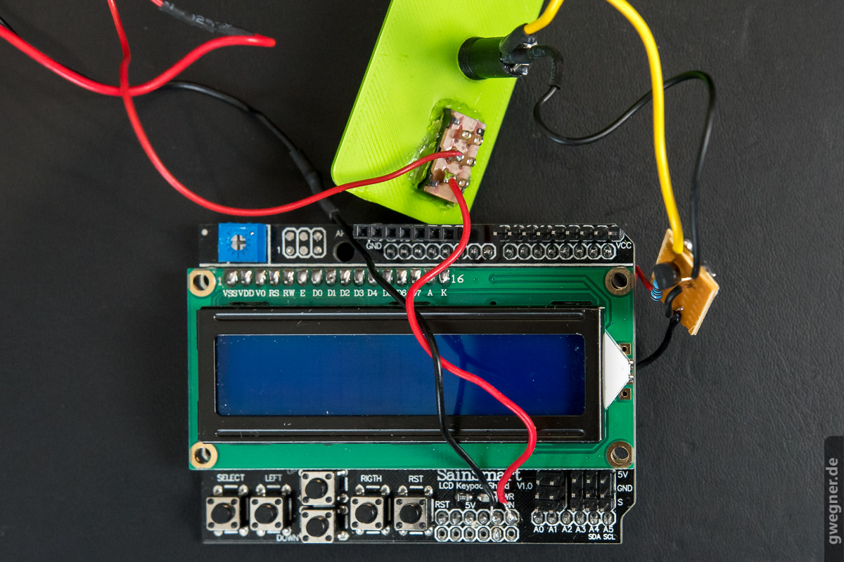
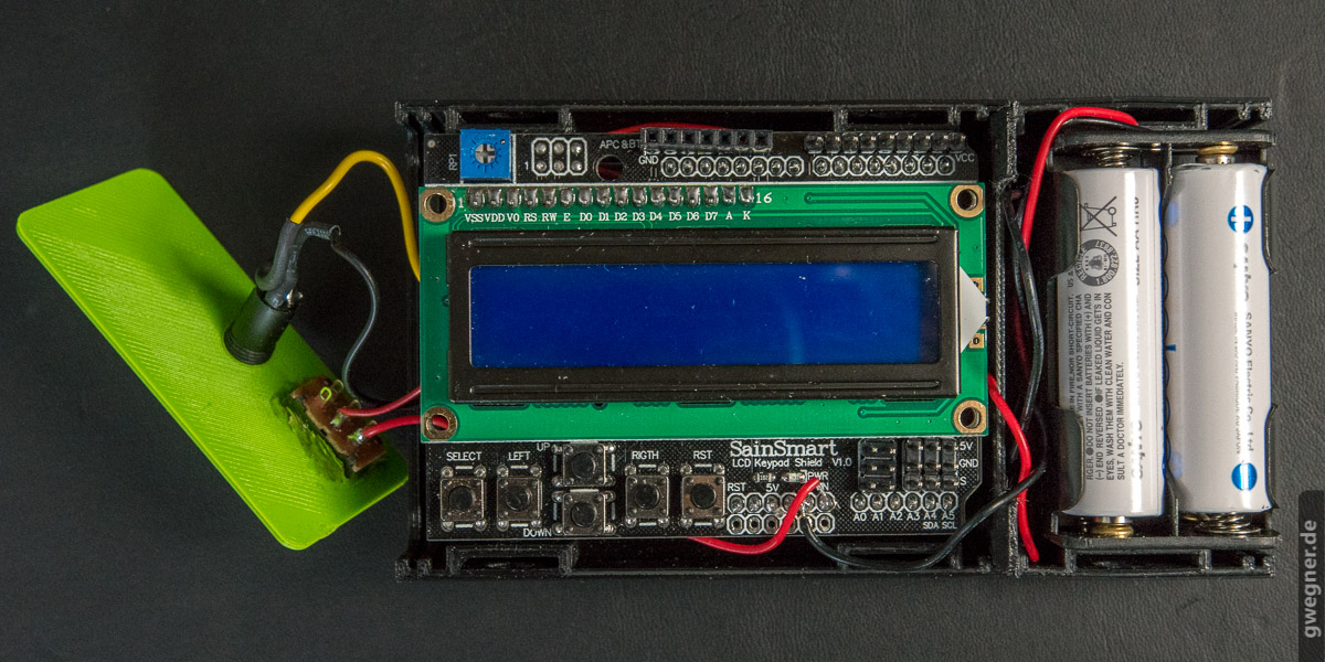
The connections for the battery holder will be soldered directly onto the Display-Shield too. That means, everything is only soldered to the Display-Shield and not to the Arduino itself.
Now please disconnect the shield from the arduino for the last time.
Solder the black wire from the battery holder to the ground pin. Now solder the red one first to the on-off switch and then connect the other pin of the on-off switch to the 5V input-pin.
If you look to the Display-Shield from the top, you will find those pins in the connection block on the right hand side of the buttons. The 5V input pin is the pin at the very right and ground is left of it, as you can see in picture.
Note: the lower “holes” are not electrically connected. If you solder the wires to those holes, you will have to use a bit & more tin to make contact with the corresponding pin above.
Please solder quickly and carefully to avoid any short circuits and overheating, which could burn the shield.
Here is an overall view of the whole unit without Arduino. The hole for the on/off-switch of this prototype was made the quick and dirty way, by melting it with a soldering iron into the housing, I’m sure you can make that better … 😉 Also take care that you place the holes for the socket and the switch in an area, which has room inside the the housing and not directly in front of the USB port on the board, otherwise it might not fit later during assembly.
Before you connect the Arduino to the display shield for the last time you should insulate the small circuit board with some gaffer tape or insulating tape. It will then be positioned between Arduino and Display-Shield. Now carefully press the display shield onto the arduino board for the last time.
The Housing
Christian Steinkrüger, the founder of Logodeckel.de, has developed a great housing for the LRTimelapse Pro-Timer Free. He is a master when it comes to 3D modeling. He really designed a fancy piece of work and furthermore, he also did a visualisation of it. But have a look yourself:
He offers the construction plans for free. If you have a 3D printer or you have access to one you can print the housing yourself. You can download the material here:
Download “LRTimelapse Pro Timer Free - Case”
LRTimelapse_Pro_Timer_Case.zip – Downloaded 9106 times – 1.47 MBIf you don’t have a 3D printer, you might probably know someone who has one. If not, most likely you will find a 3D printing service in your country.
If you can’t find any solution, users from Germany, Austria and Swizerland can order one of those housings directly from Logodeckel.
- LRTimelapse Pro-Timer Free housing accent color blue
- LRTimelapse Pro-Timer Free housing accent color green
If you live in any other country, you might contact the guys from Logodeckel via email and ask, if they are willing to ship to your country. Of course, shipping prices will be higher. Finding a local printing service might be your best option.
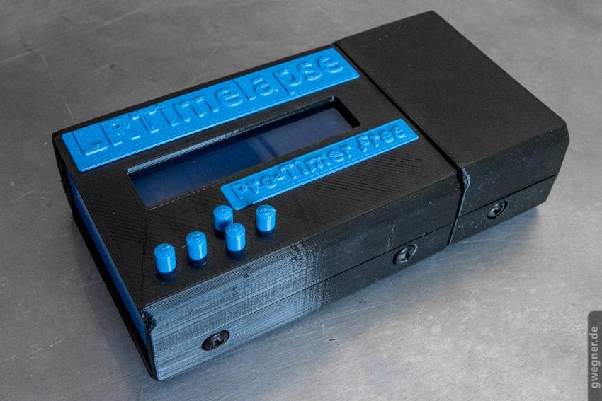
The Case from ‘Logodeckel’ with accent color blue
Now you only have to assemble all parts and to place the circuit board in the housing.
Make sure that the circuit board fits correctly into the 4 holes and the small buttons of the housing. Furthermore take care that the shield and the Arduino stick together properly. Sometimes it might be necessary to file down the contacts of the buttons on the display shield right above the DC-Input barrel jack to get a better fitting.
Also take care that no wires are pinched during assembly of the housing. The cable of the battery compartment can just be put through.
Please insert the left side cover with the connections now, the right side cover, and then the cover of the battery compartment.
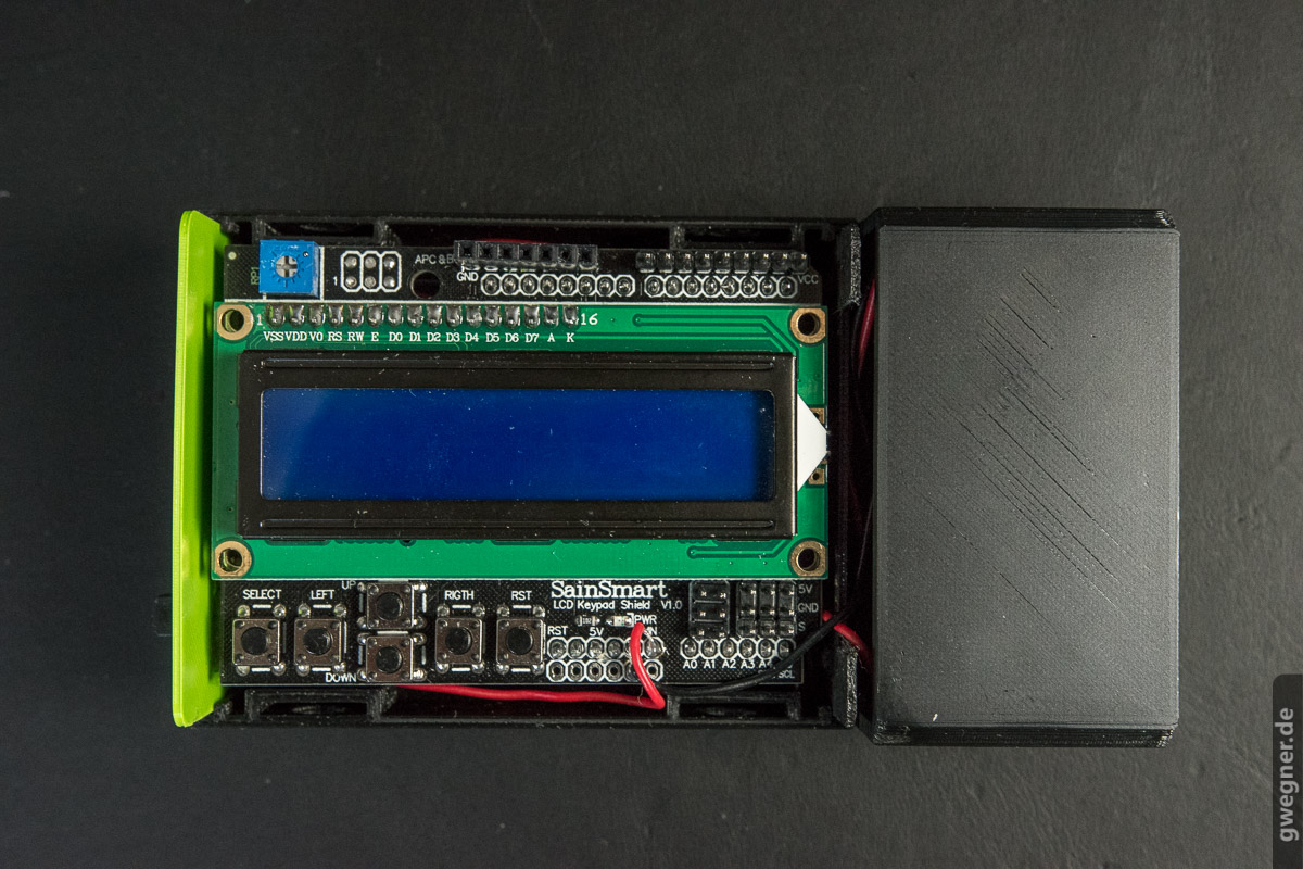
To finish, insert the buttons in the cover and close the housing. Now you can fix the housing carefully with 6 computer drive screws and that’s it. If you did everything correctly, it should fit together perfectly.
To change the battery you just need to loosen the two screws of the battery compartment and lift the small cover.
Use LRTimelapse Pro-Timer Free when shooting timelapse with motion control
When shooting timelapses from a slider and/or pan-tilt head, the camera usually will be triggered by the motion controller. That means you won’t be able to use interval ramping, which is especially useful for day to night timelapses.
With the LRTimelapse Pro-Timer Free, you can now combine both, as long as your motion controller supports “slave mode” or can be externally triggered. At the moment, this is the case for Emotimo devices (including Spectrum), the NMX from Dynamic Perception and others.
- Connect the release exit of the LRTimelapse Pro-Timer Free with a TRS-cable (2.5mm trs on both ends) with the Aux-input of the motion controller.
- Next, connect the camera port of the motion controller to your camera using the standard release cable.
- Now activate the slave mode on your controller.
- For the NMX you press the blue button of the controller three times quickly.
- For the Emotimo Spectrum, you just put the controller in pause mode after having programmed it to enable slave.
When in slave mode, the controller will wait for an external trigger before triggering a move. The trigger will be coming from the LRTimelapse Pro-Timer Free. In that way, you can use all options of your new intervalometer, while capturing pictures with motion control as well. It could not be simpler.

Conclusion
I’ve worked with the prototype of the LRTimelapse Pro Timer Free for a few months now and can’t imagine timelapse photography with another intervalometer.
Advantages are the very fast shooting without any delay on the camera, the opportunity to use intervals of 1.5 or 2.5 seconds, the display showing all the necessary information, the interval ramping feature, and last, but not least, the opportunity to switch off the lighting are features which I had always wished I had. Even the operation with gloves in the cold of Norway worked perfectly.
But you know, if nobody listens to your wishes, sometimes the only solution is to help yourself… 🙂
Speaking of cold: at very low temperatures the LCD can become somewhat slower in responding. Up to a certain level you can still operate it, but it does not like extended usage below 0°C. The Arduino still works but operating becomes more and more difficult as the display starts to get really slow. At this point, instead of keeping it attached to the camera, you should use a micro TRS extension cable and keep your LRTimelapse Pro Timer Free safely in your bag while shooting.
Community project and interaction
I understand the LRTimelapse Pro Timer Free is a community project. I would like to give it to you, the timelapse community, as something which helps you to make even better shots!
I am glad to receive your input. If you have any ideas to further development, the best would be concrete ones, such as code changes or concrete tips. Please let me know! Once you have built your own intervalometer and have tips for others, no matter how trivial, please let the community know. Your ideas will make this project get even better! I am not able to support this project as intensively as my LRTimelapse software. And I am not an Arduino expert either – it was the first time ever that I built and coded something like this. But I had a lot of fun doing it, that’s for sure!
Update: The LRTimelapse Pro Timer Free Scetches (Arduino source code) is now available on Github for your contribution!
I invite you to use the Forum which I’ve set up to discuss the many ways the LRTimelapse Pro Timer can be used and improved.
Forum to discuss about the LRTimelapse Pro-Timer Free
→ Go to the LRTimelapse Pro-Timer Free Forum
And now have a lot of fun building and using the LRTimelapse Pro-Timer Free!
Terms of License
We provide the Arduino Sketch and the housing of the LRTimelapse Pro-Timer Free under a modified Creative Commons BY-NC-SA license.
Specifically: under the condition of attribution (based on the LRTimelapse Pro-Timer Free by Gunther Wegner, housing by Christian Steinkrüger) and the exclusion of commercial usage, the source code (sketch) and the housing of the LRTimelapse Pro-Timer Free may be modified and passed on. The original logos always have to remain on the housing.
Any modification must be a) announced to the author (Gunther Wegner, support(at)lrtimelapse(dot)com) prior the its publication and made available in order to possibly be incorporated into the LRTimelapse Pro-Timer Free, and b) also be published as a free project under the same conditions.
This License applies solely to the source code and the housing of the LRTimelapse Pro-Timer Free and not to any work created by using the LRTimelapse Pro-Timer Free. These are, of course, subject to the copyright of the photographer and may be freely, even commercially, licensed and used.
Disclaimer
The construction and the use of this solution is done at your own risk. In all my tests everything worked out very well and I have confidence in my cameras to this solution. No liability nor guarantee for fit for purpose will be taken for the construction, assembly, integration, adaptation or installation of this product.
Thank you!
My special thanks go to Christian Steinkrüger and Stefan Nitz, who immediately agreed to support the project and its free character. Christian with the design of the great housing and Stefan with the offer to print the housing and to offer them almost at cost.
My big thank you goes also to the community, who helped translate and proofread the english version of this article, namely:
Monika Meier, Moritz Plingen, Manuel Schröder, Daniel Rabinovich, Daniel Gierig, Dominik Becker, Daniel Rabinovich, Bertram Lütke, Dennis Yarbro, Kevin Lewis, Gary Bakker, Steve McCarthy, Sean Doherty, Kevin Rank, Greg McCall, Susie Palermo G, Ray Hamilton, Murray Wayper and others.